Showing posts with label Arduino. Show all posts

Jun 5, 2021

[Arduino code] limit switch (Endstop switch) (리미트 스위치, 엔드스탑 스위치)

- Supplies: limit switch, Arduino board

- How to connect and the result of serial monitor.


- Example code

#define limit_switch_pin 2

void setup() {
  // put your setup code here, to run once:
  // switch pin setting
  Serial.begin(9600);
  pinMode(limit_switch_pin, INPUT);
 
}

void loop() {
  // put your main code here, to run repeatedly:
  if(digitalRead(limit_switch_pin) == LOW){
    Serial.println("Switch close");
  }else{
    Serial.println("Switch open");
  }
}


Dec 10, 2020

[Arduino code] Proportional-Integral-Differential control (PID control)

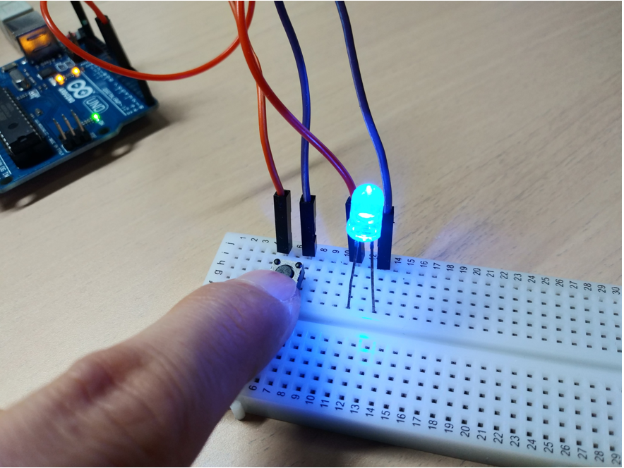
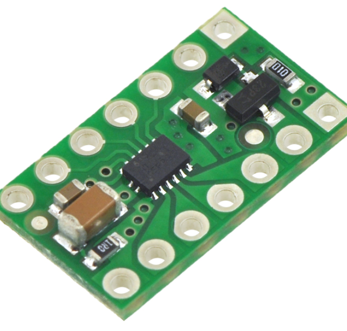
- Supplies: Arduino board, ... sensor, ... actuator

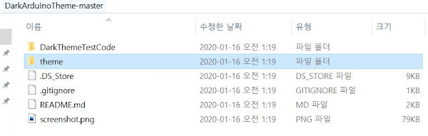
- Comment: I use 'AutoPID' library and this code is based on the bottom *site.

*https://r-downing.github.io/AutoPID/

- How to install a PID library?

Sketch-> Include Library -> Manage Libraries... -> Write 'pid'


- Example code:

#include <AutoPID.h>

#define p_gain 1
#define i_gain 1
#define d_gain 1

//Min and Max values depend on your actuator function code. 
#define control_input_min -255
#define control_input_max 255

// unit: milliseconds
// ex) 20 ms => 50 Hz
#define control_interval 20 

double measured_value, desired_value, control_input, value_from_sensor;

AutoPID PID_control(&measured_value, &desired_value, &control_input, control_input_min, ...,
control_input_max, p_gain, i_gain, d_gain);
void setup() {
  // put your setup code here, to run once:
  PID_control.setTimeStep(control_interval);
}

void loop() {
  // put your main code here, to run repeatedly:

  desired_value = 0; //It depends on your tasks.
  measured_value = value_from_sensor; //It is measured by sensor, so its type depends on your sensor.
  PID_control.run();
  //Then, 'control_input' is calculated and its value drives your actuators.
  //So, you need to insert your actuator function code to the bottom side.
  //ex) move(1, 1, control_input);
  
}


Dec 8, 2020

[Arduino code] 9-axis IMU sensor MPU-9250 (9축 IMU 센서)

- Supplies: *IMU sensor (MPU-9250), Arduino board

* https://learn.sparkfun.com/tutorials/mpu-9250-hookup-guide/all

- How to connect?!


- Example code: The bottom code is based on the *Sparkfun-site and I revised the original code as a simple version.

#include "quaternionFilters.h"
#include "MPU9250.h"

#define AHRS true         // Set to false for basic data read
#define SerialDebug true  // Set to true to get Serial output for debugging

// Pin definitions
int intPin = 12;  // These can be changed, 2 and 3 are the Arduinos ext int pins
int myLed  = 13;  // Set up pin 13 led for toggling

#define I2Cclock 400000
#define I2Cport Wire
// Use either this line or the next to select which I2C address your device is using
#define MPU9250_ADDRESS MPU9250_ADDRESS_AD0   
//#define MPU9250_ADDRESS MPU9250_ADDRESS_AD1 MPU9250 myIMU(MPU9250_ADDRESS, I2Cport, I2Cclock); #define measure_period 100 //1000ms = 1sec unsigned long current_time; void setup() { Wire.begin(); // TWBR = 12; // 400 kbit/sec I2C speed Serial.begin(38400); while(!Serial){}; // Set up the interrupt pin, its set as active high, push-pull pinMode(intPin, INPUT); digitalWrite(intPin, LOW); pinMode(myLed, OUTPUT); digitalWrite(myLed, HIGH); // Read the WHO_AM_I register, this is a good test of communication byte c = myIMU.readByte(MPU9250_ADDRESS, WHO_AM_I_MPU9250); Serial.print(F("MPU9250 I AM 0x")); Serial.print(c, HEX); Serial.print(F(" I should be 0x")); Serial.println(0x71, HEX);

Dec 1, 2020

[Arduino code] Express number using FND display module TM1637 (디스플레이 모듈을 이용한 숫자 표기)

- Supplies: *FND display (SZH-EKBZ-016), Arduino board
- 준비물: FND 디스플레이, 아두이노

*https://www.devicemart.co.kr/goods/view?no=1326952

#include <TM1637Display.h>

#define baud_rate 9600
#define CLK 9
#define DIO 10


TM1637Display dsp(CLK, DIO);

void setup() {
  Serial.begin(baud_rate);
  Serial.println("Serial Start");

}

void loop() {

  dsp.setBrightness(5); // brightness: 0 ~ 7
  double number = 123;  
//  dsp.showNumberDec(number); 
//  dsp.showNumberDec(number, true); 
//  dsp.showNumberDecEx(number, 0x40);
//  dsp.showNumberDecEx(number, 0x40, true);
  
}


Top left: dsp.showNumberDec(number);  Top right: dsp.showNumberDec(number, true);
Bottom left: dsp.showNumberDecEx(number, 0x40);, Bottom right: dsp.showNumberDecEx(number, 0x40, true);


Nov 30, 2020

[Arduino code] Find an I2C address of a sensor using I2C scanner (IC2로 통신하는 센서의 주소 찾기)

- Supplies: Arduino board, I2C sensor
- How to connect?!

- Example code
#include <Wire.h>
 
 
void setup()
{
  Wire.begin();
 
  Serial.begin(9600);
  while (!Serial);             // Leonardo: wait for serial monitor
  Serial.println("\nI2C Scanner");
}
 

Nov 26, 2020

How to build Arduino IDE for Visual Studio 2019 (Visual Micro) (Visual Studio 2019에서 Arduino IDE 사용하기, 개발환경 구축)

Installation methods can be dependent on your program version.

0. First, install Visual Studio 2019.

1. In Menu bar, Click [Extensions]->[Manage Extensions].


2. Write 'arduino' -> Clink Download.


3. In the Pop-up window, Clink the ok button.

4. Restart the VS program and Clink the 'Create a new project'.


5.  Write 'arduino' and Clink the 'Arduino Empty Project'.


6. Write the Project name (ex) VS_Arduino_example).


7. Write some code in the blank sheet and check the version, board, and port. After then, click the upload button.


* You can find some example codes in the red marked button. 

Nov 19, 2020

[Arduino code] Moving average filter (아두이노에서 구현한 이동평균 필터)

- Simple Arduino code to implement a moving average filter
- 이동평균 필터를 구현한 아두이노 코드
#define baud_rate 9600
#define low_window_size 5
#define high_window_size 20
//...
//...
int low_index = 0;
int high_index = 0;

float low_readings[low_window_size];
float high_readings[high_window_size];

float low_sum_measurement = 0;
float high_sum_measurement = 0;

float low_avg_measurement = 0;
float high_avg_measurement = 0;


void setup()
{
  
  //...
  //...
 Serial.begin(baud_rate); 
 //initialize **************************************************************
  for(int i = 0; i<low_window_size; i++){
    low_readings[i] = 0;
  }
  for(int k = 0; k<high_window_size; k++){
     high_readings[k] = 0;
  }
 
}

void loop()
{

  //...
  //...

  //moving average filter ***************************************************
  low_sum_measurement = low_sum_measurement - low_readings[low_index];
  high_sum_measurement = high_sum_measurement - high_readings[high_index];

  // sensor measurement
  low_readings[low_index] = measurement;
  high_readings[high_index] = measurement;
  
  low_sum_measurement = low_sum_measurement + low_readings[low_index];
  high_sum_measurement = high_sum_measurement + high_readings[high_index];
  
  low_index = low_index + 1;
  high_index = high_index + 1;

  if(low_index>=low_window_size){
    low_index = 0;
  }
  if(high_index>=high_window_size){
    high_index = 0;
  }

  low_avg_measurement = low_sum_measurement/low_window_size;
  high_avg_measurement = high_sum_measurement/high_window_size;
  
  // serial display ********************************************************
  Serial.print(measurement); Serial.print(", ");
  Serial.print(low_avg_measurement); Serial.print(",  ");
  Serial.print(high_avg_measurement);
  Serial.println();

}

As 'window size' increases, noise decreases but a time delay occurs.
window size 가 커질수록 노이즈는 줄어들지만 시간 지연 현상이 발생한다.

Nov 2, 2020

[Arduino project] Infrared (IR) control module kit using Arduino Uno

- Goal: Check the button address of IR remote controller. (IR 조종기의 버튼 주소 확인)

- Supplies: Arduino Uno, IR kit (ELB030102 (YwRobot), ...)

- 준비물: 아두이노 우노, 적외선 실험 키트

https://www.devicemart.co.kr/goods/view?no=1280305#goods_description

1. You need to install Arduino IR library. (아두이노 IR 라이브러리 설치 필요.) 

2. Arduino code: File => Example => IRremote => IRrecvDumpV2


3. Connect three output pins of the IR receiver to Arduino Uno.


4. Push the two buttons (ex. CH, 100+) of the IR transmitter.

Oct 8, 2020

[Arduino project] robot arm control using servo motors and potentionmeters (서보모터와 가변저항을 이용해 만든 로봇팔 제어)

- Supplies: Servo motor (SG90), wood stick, potentiometer, Arduino board 

- 준비물: 서보모터, 나무 막대기, 가변저항, 아두이노 보드


The operation principle is that the signal generated by each potentiometer is directly sent to each servo motor, So the servo type robot arm moves based on the control signals from the potentiometer type robot arm.

가변저항기에서 생성된 제어신호가 서보모터에 전달되어 서보모터로 만든 로봇팔이 가변저항기로 만든 로봇팔의 동작을 따라한다. 


Aug 14, 2020

How to change dark theme for Arduino IDE? (어두운 계열로 아두이노 IDE를 바꾸는 방법)

 
1. Download the .zip file from the site below. 

https://github.com/jeffThompson/DarkArduinoTheme

2. Unzip the file downloaded.
 

3. Paste (overwrite, 대상 폴더의 파일 덮어쓰기) the theme folder in the extracted folder to the Arduino path installed. ex) C:\Program Files (x86)\Arduino\lib 

[Before Arduino IDE theme]
[After Arduino IDE theme]

Jun 1, 2020

[Arduino code] Motor/Servo RPM measurement using photodiode (아두이노에서 포토다이오드를 이용한 모터/서보모터 RPM 측정)

- RPM measurement of motor/servo motor using photo diode.
- 포토 다이오드를 활용한 모터/서보모터의 RPM 측정.
- Sensor: SZH-EKAD-109
https://www.devicemart.co.kr/goods/view?no=1329652

- 원리
포토 다이오드: 빛에너지 -> 전기에너지
발광 다이오드: 전기에너지 -> 빛에너지
https://youtu.be/SFc673lEyQA

- 코드
const byte interruptPin = 2;
volatile int pre_count, count;
unsigned long skip_milli_time = 100; 
unsigned long cur_time = 0;
unsigned long pre_time = 0;

May 5, 2020

[Myduino] Customized Arduino UNO PCB board (자작으로 만든 아두이노 PCB 보드)


How to make your own Arduino?!


Components:
 1. ATmega328P-PU (1)
 2. 16 Mhz crystal (1)
 3. 10 kΩ resistor (1)
 4. 22pF capacitor (2)
 5. 100nF capacitor (1)


A circuit that looks complicated as shown below can be easily implemented with a PCB board.


(left) board, (right) 3D image


Apr 5, 2020

[Myduino] Customized Arduino UNO (자작으로 만든 아두이노)

How to make your own Arduino?!

Component:
 1. ATmega328P-PU (1)
 2. 16 Mhz crystal (1)
 3. 10 kΩ resistor
 4. 22pF capacitor (2)
 5. 100nF capacitor (1)
 6. LED (1)
 7. Breadboard (1)
 8. Jumper wire (many)
 9. FTDI USB port (1)

       <ATmega328P and Arduino Uno Pin Mapping>

                                <Wire connection>


Mar 31, 2020

[Arduino code] the output of Serial.write() and Serial.print() (아두이노에서의 시리얼 모니터 출력 예시)

- Check the output result of Serial.write(val) and Serial.print(val) functions according to data types.
(자료형에 따른 Serial.write(val)와 Serial.print(val) 함수의 출력결과 확인)
 : In the case of Serial.write(val), the character corresponding to the ASCII code of val is output regardless of the data type of val.
(Serial.write(val)의 경우 val의 자료형에 상관없이 val의 아스키코드에 해당하는 문자를 출력)
 : Use Serial.write(val) function for characters, and Serial.print(val) function for numbers.

unsigned int bd_rate = 9600;

void setup() {
  // put your setup code here, to run once:
  Serial.begin(bd_rate);
  Serial.println("Serial START");
}

void loop() {
  // put your main code here, to run repeatedly:
  char X = 97;
  int Y = 97;
  Serial.print("X: "); Serial.print(X);Serial.print("\t"); Serial.write(X); Serial.println();
  Serial.print("Y: "); Serial.print(Y); Serial.print("\t"); Serial.write(Y); Serial.println();
  delay(1000);
}
<Snap shot of Arduino serial moniter>

Dec 11, 2019

[Arduino code] First order Low pass filter (LPF) (아두이노에서 구현한 1차 저역 통과 필터)

- Simple Arduino code to implement a 1st Low pass filter (LPF)
- 1차 저역 통과 필터를 구현한 간단한 아두이노 코드

double pre_value_1 = 0;
double pre_value_2 = 0;
double pre_time = 0;
//Set the LPF parameter
double tau_1 = 30;
double tau_2 = 100;
void setup() {
  // put your setup code here, to run once:
  Serial.begin(9600);
  Serial.println("Low pass filter starts!");
}

void loop() {
  // put your main code here, to run repeatedly:
  double st_time = millis();
  double dt = (st_time - pre_time);   

Nov 1, 2019

[Arduino code] LED turn on/off using a switch (스위치를 이용해 LED 켜고/끄기 아두이노 예제)

- Supplies: Arduino, LED, switch, jumper wire, breadboard
- 준비물: 아두이노, LED, 스위치, 전선

Connected configuration (연결 상태)

           
           Turn off (LED 끄기)
Turn on (LED 켜기)

// LED pin #
int LED_pin = 3;

// Switch pin#
int switch_pin = 5;

void setup() {
  // put your setup code here, to run once:
  pinMode(LED_pin, OUTPUT);
  pinMode(switch_pin, INPUT_PULLUP);

}

Oct 1, 2019

Pololu single motor driver - DRV8838 - Arduino code (모터 드라이버)


- Simple Arduino code to operate a DC motor with the motor driver.
- 1개의 DC 모터를 구동시키기 위해 모터 드라이버를 이용하는 간단한 아두이노 코드.
int Enable_pin = 9;
int Phase_pin = 8;

void setup() {
  // put your setup code here, to run once:
  pinMode(Enable_pin, OUTPUT);
  pinMode(Phase_pin, OUTPUT);
}

Apr 23, 2019

Pololu dual motor driver - DRV8835 - Arduino code (모터 드라이버)


- Simple Arduino code to operate two DC motors with the motor driver.
- 2개의 DC 모터를 구동시키기 위해 모터 드라이버를 이용하는 간단한 아두이노 코드.

Apr 19, 2019

Arduino PWM signals - analogWrite() (아두이노 PWM 신호)

[Readme]
Arduino (ATmega168 or ATmega328P)

- analogWrite() function works on pins 3, 5, 6, 9, 10, and 11.

- On the Uno, pro-mini and etc, pins 5 and 6 have a 980 Hz as PWM frequency and the others is 490 Hz.

- If you use the <Servo.h> library, you cannot use analogWrite() function on pins 9 and 10. In other words, you cannot drive some servo motors on pins 9 and 10 using analogWrite() function.

---------------------------------------------------------------------------------------
analogWrite() 함수는 핀 3, 5, 6, 9, 10, and 11 에서 동작한다.

- 우도, 프로미니, 기타등등 보드에서 핀 5와 6은 980 Hz로 PWM 시그널을 발생하며 다른 핀에서는 490 Hz로 시그널을 발생한다.

- <Servo.h> 라이브러리를 사용하게 되면 핀 9와 10에서 analogWrite() 함수를 사용할 수 없다. 즉 핀 9번과 10에서 analogWrite() 함수를 이용해 서보모터를 구동시킬 수 없다.

Apr 17, 2019

Bluetooth HC-06 ATcommand setting - Arduino code (블루투스 HC-06)

- Arduino code for HC-06 bluetooth setting and some AT commands examples in the serial monitor.
(HC-06 블루투스 모듈 세팅을 위한 아두이노 코드와 AT 명령어 사용 예시)

/////////////////////////////////////////////////////////
//main code//
/////////////////////////////////////////////////////////

#include <SoftwareSerial.h>

//4800, 9600, 19200, 38400, 57600, 115200, ...
#define baud_rate 9600

int blueTx = 2;
int blueRx = 4;

SoftwareSerial mySerial(blueTx, blueRx);

void setup() {
  // put your setup code here, to run once:
  Serial.begin(baud_rate);
  mySerial.begin(baud_rate);

  Serial.print("Bluetooth ready");
}

void loop() {
  // put your main code here, to run repeatedly:
  if(mySerial.available()){
    Serial.write(mySerial.read());
  }
  if(Serial.available()){
    mySerial.write(Serial.read()); 
  }
}